

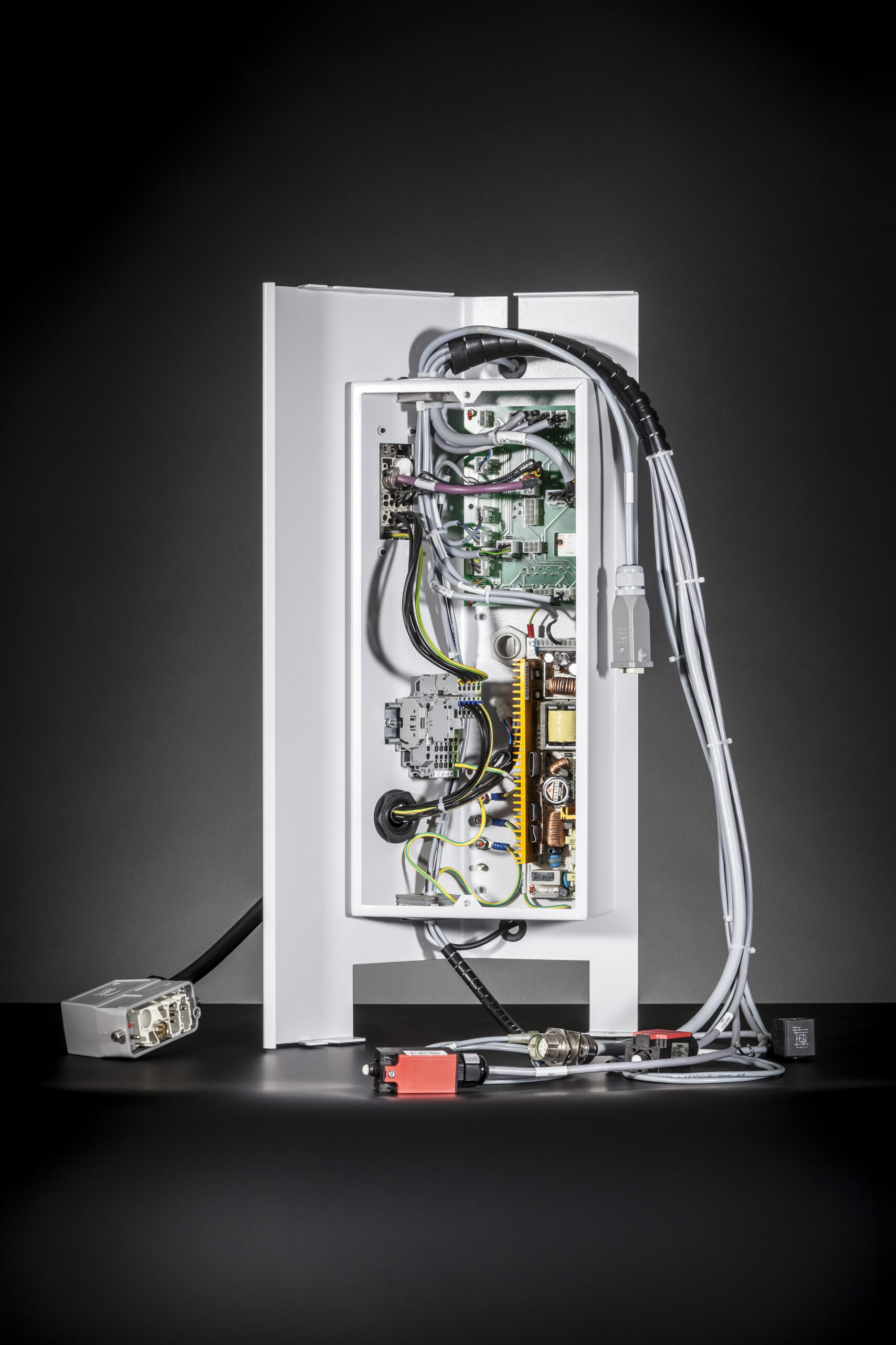


FAQ — TECHNOLOGY OF CABLE ASSEMBLIES
Frequently asked questions.
Become aware of more details of our products. Learn more about standards, backgrounds and technology aspects. For you we did prepare everything in detail, separated according to the product groups. Enjoy by reading more!
Industrial Ethernet

Industrial Ethernet is the word for an identical infrastructure within local area networks, but with a modified protocol. The protocol is not the standard Ethernet one. This is how networks exceed the office communication and integrate industrial field devices by using the same hardware platform. At the same time process security is improved by the modified protocols and your productivity stays high. There are different protocols for industrial ethernet standard, established are such as Profinet, Ether-CAT, EthernetIP, Powerlink and Sercos III with runtimes down to 100?s. Therefore protocols are capable of real-time applications and thus motion control. This standard has established in the market more and more. There are 2 pin configuration defined by the standard A and B, B is used more often. Whenever it does not come to Gigabit networks, the use of the pins 1, 2, 3 and 6 is sufficient.
Profibus
The profibus (process field bus) distinguishes between 2 different types. There are the versions Profibus DP (decentral periphery) and Profibus PA (process automation). Within the mechanical engineering the Profibus DP standard is used. This type of bus is described by the international norm IEC 61158. Profibus DP is a 2-wire bus with 9600bit/s
to 12Mbit/s adequate for distances from 100m to 1200m. This bus is used for the electrical transmission via copper in a line based infrastructure. By using fiber optics for the transmission the distances can be extended up to 15km.
Device Net
The Device Net system is commonly used in the field of industrial automation for connecting control units to one another. Device Net uses the controller area network as its basis.
Attenuation
The attenuation describes the reduction of the signal level on the cable. Therefore signal loss. To keep the attenuation low, the make-up length is supposed to be high. But this collides with inferior conditions for drag chain applications of a long make up length. See drag chain capabilities.
Can-Bus

The Can-Bus (controller area network bus) is an accepted technology applied within vehicles. It is a field bus with a string/line infrastructure, additional strings/lines are possible in a limited way. The Can-Bus has to be terminated with 120 Ohm at its ends. This is necessary to prevent signal reflections and therefore communications errors. It is also possible to set up this bus with a star topology. The Can-Bus works on basis of voltage level differences, hence this bus is insensitive for external interferences. This is due to the fact that interferences influence both signal wires inside the cable and the voltage difference continues to be the same, the signal remains stable.
In accordance to the required data performance, the length and the corresponding loop resistance result the following cross sections for Can-Bus cables:
Drag chain capabilities
In order to achieve better drag chain properties, there is worked with a twisted wire make-up. It works like this: The lower the make-up length, the higher the mechanical properties for drag chains. The reason for it is the compensation of the compressing and stretching within a single wire during drag chain motions. If the wires are not twisted, they will be damaged by the compressing and stretching in the drag chain. For drag chain applications the jacket of a cable is made generally of PUR (polyurethane).
Wave impedance
The wave impedance is usually a real value (e.g. 50 ? or 100 Ω). This value is independent regarding the cable length, but it is not independent regarding the frequency. The frequency dependency is up to the dielectric material and has to be considered for all signal transmission. Another word for it is dispersion. The wave impedance is not the ohmic resistance, it is considered to be the emitter gate resistance of a endless homogeny cable without signal reflection.
Shielding
The shielding is a electrical conductive cover for the functional wires of a cable. The shielding has 2 functions. It prevents interferences from decoupling off the cable, at the same time it prevent interferences from coupling into the cable. Both functions are equally important. There are 4 different shielding designs existing.

Would you like personalised advice?
Then get in touch with us. Our drive and industry expert Christian Gladis will be happy to advise you. Together we will find the right system for you.


CABLE ASSEMBLIES FOR DRIVE SYSTEMS.

CABLE ASSEMBLIES.

ORIGINAL EQUIPMENT
MANUFACTURER.