

FAQ — TECHNOLOGY OF LED INDUSTRIAL LUMINAIRES
Frequently asked questions.
Durability

We guarantee a durability of 60.000h for our LED luminaires. The durability is considered to be expired as soon as the light intensity decreases under 70%. The luminaire does not fail suddenly, but the light intensity lowers. In 3-shift-operation over 5 days a week we guarantee a luminosity of over 70% for 9.6 years. Additionally, LEDs are insensitive for vibrations. Usually the luminaires outlast the plant they are installed in.
Heat management


The durability of LEDs depends basically on the heat influence. Although the temperature in LEDs develops much lower than it is in other illuminates, the durability can be increased by the right heat management. To ensure this our circuit boards are made of aluminium to lead the head through the housing to the environment.
Colour fidelity Ra or CRI
The colour fidelity is also a quality criterion for LEDs. It shows the colour rendering of the emitted light. The sun light e.g. contains all prismatic parts and all colours are visible. Are some prismatic parts missing, certain colours can’t be seen. Instead of this colour dark or black parts appear. Our luminaires have a fidelity of greater than 80% i.e. Ra > 80 or CRI > 80. A well colour rendering. A colour fidelity of smaller than 60 is consider insufficient.
Comparising of well and insufficient colour fidelity

left picture: All prismatic colours are present (colour fidelity > 80
right picture: Just the green and blue parts auf the light are present (colour fidelity < 60)
Energy efficiency
A light bulb has a light efficiency of up to 12 lm/W, a fluorescent lamp up to 100 lm/W. Today LEDs achieve a light efficiency of up to 180 lm/W with markedly longer durability. The unit lm/W shows the relation between emitted luminous flux and entered power of the illuminate.
Binning

Because of the manufacturing process the achievement of a consistent colour temperature is extremely difficult. To guarantee a consistent colour appearance the diodes get clustered in a CIE normed colour system. This is called binning.
The CIE normed colour system covers all visual colours and shows the relation between colour and colour valence. In this colour system an ANSI BIN grid is covering the white
area. By this grid the coordinates of the colour temperatures are defined, screened and name in the CIE normed colour systems. The ANSI BIN system is divided in areas from Q to H, whereby every area is divided into 6 cells, except Area A, which is divided in 8 cells. The area A describes the colour temperature at 7.000K and 6.500K. H completes the white area with 2.600K.
White LEDs
There are no LEDs emitting white light. LEDs themselves emit blue light, which is conducted through a phosphorous layer. This phosphorous layer completes the prismatic parts of the blue light, giving it a white appearance.
Weve length

The wave lengths of every single LED are located between 400 and 800nm. At 450nm and between 500 and 650nm are emission peaks.
Ergonomics
Light can also contribute to ergonomics. One advantage of diodes is the consisted and flicker free light emission, which prevent fast fatigue at work place. Additional conventional luminaires have just one light source, therefore just one shadow. The luminosity of LEDs is achieved by many small LEDs. Thereby it depends on the construction of the luminaire whether this circumstance leads to multiple shadows. Just think about floodlight on a football ground: four floodlights means four shadows of one player. The same effect may occur with LEDs, despite of the same light direction. On work places the employee can be impeded by multiple shadows of his hand. The numbers of shadows depend on the number of LEDs. The right design of a luminaire can prevent multiple shadows from happening.
Radiation angle

The radiation angle is 120°, if not otherwise specified. There are LED luminaires with optics with 30° or 60° for a focussing illumination. A lens bunches the light and prevents a normal dispersion. The radiation angle alpha means the angle of the spread light. The outer limits result at 50% light intensity.
Photo-biological safety
All electrically driven incoherent wide-band radiation need to intend the international standards for photo-biological safety. Thus LEDs but not laser light. Thereby the relevant area of wave length extends from 200nm to 3000nm. Our LEDs emit in the range from 200nm to 800nm and have to apply the standards DIN EN 62471. There are two kinds of hazards: the photo-chemical and the thermic retina hazard. The decisive parameters are the prismatic ray density and radiant intensity. For classification there are 4 risk classes: the free class, risk class 1 (low risk), risk class 2 (middle risk), risk class 3 (high risk). Our LED luminaires are to be assigned to risk class 1. Our LEDs fall short of the normative limits.
Protection type
The protection type contains two code numbers. The first code number describes the protection of product against ingress of solid foreign bodies. The second code number describes the protection of the product against the ingress of liquids.
Suppressor circuit
In case of overvoltage and transients our luminaires have an ESD-protection on the board. This additional semiconductor prevents the luminaires of damages by encoupled exterior signals and transients of a low voltage level.
Protection class

LED luminaires with 24V operation voltage are assigned protection class III and are therefore supplied with protective extra-low voltage. The operation voltage is too low to cause mortal danger. Beside protection class III there is further class II for protective insulation devices and class I for such with protective earth connection. The description of protection classes pictures the way mortal danger is prevented.
Testing according to luminaire standard
Ageing test / cyclic test:
The luminaire operates at +10°C 240h with a brake of 3h every 21h. At the same time the power supply is located in the same room like the luminaire. The test is considered passed, if there is no deformation, the luminaire is still working and all inscriptions are still readable.
Heating test
This test prevents the user of injuries. The luminaire operates therefore at maximum ambient temperature and if possible in a thermal unfavourable situation. The voltage is constant with a tolerance of +/-1%. When the temperatue of the luminaire surface does not change more than 1°C per hour, the measurement starts. This is called steady-state. The standard table defines measured points and limit values. The test is considered to be passed, if the limit values are not exceeded more than 5°C.
Eco-Modus
Lots of luminaire types have an Eco-Modus feature. The Eco-Modus can be controlled by Pin 2 of the connector respectively the additional connecting wire. So the luminaire is dimmed and emitts 30% of it nominal luminous flux. Therefore machine workplace can be made more ergonomical and additionally more energy efficiently. The machine interior, for example, can be subdued luminated during processing and fully illuminated when the door opens and the operator enters the machine.
Optik (TIR)

The TIR principle is the basic principle of optics. TIR means “total internal reflection” and describes the physical principle of reflection when light beams meet the surface of a media towards another one. There is an critical angle between internal reflection and exit angle. Impinges a light ray flatter on the interface than the critical angle, the light beam does not exit the medium and reflects totally internally. If the light beam exits the medium, it diffracts when not impinging on the surface in a 90° angle.
Application
Not every luminaire is suitable for every application. Especially the choice of material for the transparent coverage has to be considered. Deployed are the materials PMMA and single-pane safety glass (ESG).
Chipping process
If the contact to fly-around chips can`t be avoided, it`s advisable to choose ESG as coverage. If a coverage like PMMA would be chosen, hot chips could cause stigmas and therefore non-transparency.
Cooling liquids and lubricants
For the use of cooling liquids and lubricants a ESG cover is recommended. The material PMMA does not absorb cooling liquids and lubricants anymore, like it was in the past. But the light intensity decreases by stigmas, when hot chips meet the translucent surface.
Food and beverage industry
The application of ESG is not allowed. There has to be used a certified PMMA, adequate for the contact with food, according to FDA. Attention should be paid to hygiene standards of the DIN EN 1672-2 for safe and easy cleaning as well.
Conformity and standards

With the requirements of the European Commission, industrial luminaires have to comply with the harmonized standards DIN EN 55015 (EMV), DIN EN 61547 (EMV), DIN EN 60598-1 (general requirements and tests) and DIN EN 62471 8photobiological safety) and fulfill thereby the European directive for low voltage and EMC. By using the CE labelling we commit to all related harmonized harmoniously standards.
Stroboscopic effect
With the requirements of the European Commission, industrial luminaires have to comply with the harmonized standards DIN EN 55015 (EMV), DIN EN 61547 (EMV), DIN EN 60598-1 (general requirements and tests) and DIN EN 62471 8photobiological safety) and fulfill thereby the European directive for low voltage and EMC. By using the CE labelling we commit to all related harmonized harmoniously standards.

Would you like personalised advice?
Our product expert Alexander Sangel will be happy to advise you. Together we will find the right connection for you.


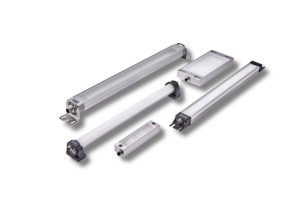
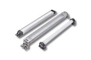
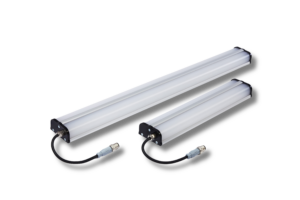
LED MACHINE LUMINAIRES.

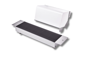
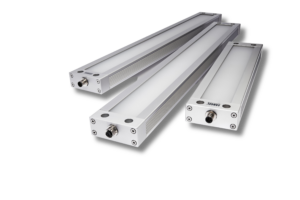
LED SIGNAL LUMINAIRES.

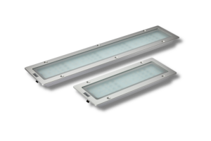
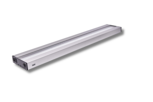
LED WORKSTATION LUMINAIRES.